It is a mandatory requirement of the National Construction Code that all buildings, including architectural elements and service components such as suspended ceilings, be designed to withstand earthquake loads. All non-structural components and their associated connections, including suspended ceiling systems, must be designed to resist horizontal and vertical earthquake forces in accordance with AS 1170.4 Clause 8.0
Does your project require seismic assessment?
According to the National Construction Code (NCC), all buildings and their components require a seismic assessment to ensure they meet the seismic design requirements.
The extent of these requirements is determined based on the Importance Level of the building, which is defined by the NCC and ranges from 1 to 4. The table below outlines the definitions of the various Importance Levels across different types of buildings.
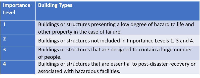
Importance Level 1 structures and buildings, including domestic structures that comply with the definition in Appendix A of AS 1170.4, are not required to be designed for earthquake actions and are deemed to satisfy the AS 1170.4 standard. Other Importance Level 1 buildings and domestic structures that do not comply with the limits specified in Appendix A of AS 1170.4 must be designed for earthquake actions as Importance Level 2 structures
For Importance Level 2 or higher, buildings and their components (including non-load-bearing walls and ceilings) must be designed to withstand seismic loads, in addition to other loads such as wind and operational or functional loads.
Serviceability limit states are deemed satisfied for seismic loading in Importance Level 1, 2, and 3 structures designed in accordance with AS 1170.4. For Importance Level 4 buildings, such as major hospitals or data centres essential for post-disaster recovery, a special study must be conducted to ensure the buildings remain serviceable for immediate use after an earthquake, similar to those associated with Importance Level 2 structures.
Seismic Ceiling Design Procedure
Australian Standard AS1170.4 `Earthquake actions in Australia’ provides the method of assessing the seismic actions based on the following parameters:
- Building Importance Level (IL)
- Site sub-soil class
- Probability factor (Kp)
- Site hazard factor (Z)
- Structure height (hn)
Using the above parameters, the project Earthquake Design Category ‘EDC’ can be calculated using Table 2.1 of the Australian Standard AS 1170.4 which will be used to set the Design Procedures for the Earthquake Actions.
Non-structural parts or components including ceiling framing and their attachments shall be designed to resist the horizontal earthquake force determined in accordance with Clause 8.3 of Section 8.0 of the Australian Standard AS 1170.4. Horizontal earthquake force shall be applied to the component at its centre of mass in combination with the gravity load of the element.
Suspended ceiling systems, such as exposed grid framing with tiles or suspended framing concealed with plasterboard, are two common examples used in commercial building construction.
The horizontal earthquake loading, proportional to the mass of the ceiling, must be absorbed by the grid framing and its fixings to the primary structure. The framing and fixings should be designed and detailed to withstand the ultimate seismic ceiling load. The ceiling lining, whether solid plasterboard or an exposed grid of tiles, also plays an important role as a ceiling diaphragm, distributing the seismic load evenly to the framing. A standard 13mm plasterboard lining is generally considered rigid enough for this purpose.
There are generally two options for transferring seismic loading from suspended ceilings to the primary structure:
- Seismic ceiling with perimeter fixings
- Seismic ceiling with plenum bracing
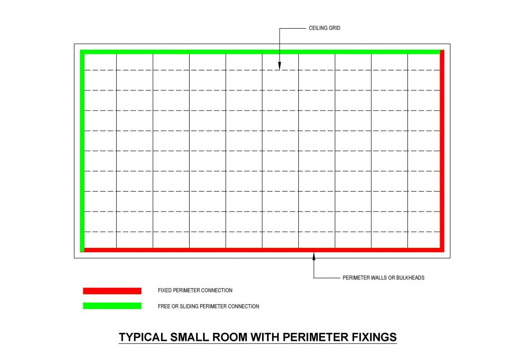
Seismic Ceiling with Perimeter Fixings
The ceiling framing is suspended using hanger rods which shall be designed to take the vertical load. The vertical load should be combination of dead load of the lining and framing as well as distributed service load of up to 3 kg/m2 (as per AS 2785) under seismic conditions.
A suspended ceiling must not be used to support any plant or equipment weighing over 10 kg. Such plant or equipment located within the ceiling space must have independent support and maintain the required clearances. When equipment is supported by a suspended ceiling, it should be securely and positively attached to the ceiling suspension system and not the panels or tiles.
The lateral or horizontal seismic loading shall be taken by the grid framing and their fixings to the adjacent wall framing. the suspended ceiling system us screwed fixed to the perimeter on two adjacent sides, with sliding connections on the opposite sides. Seismic loads are transferred from the ceiling to the perimeter through the fixings on two sides. Depending on the seismic loading, ceiling mass and capacity of the fixings to the side walls, the maximum length of the room (without plenum bracing) will be calculated in each direction so the maximum room size will be calculated.
Seismic Ceiling with Plenum Bracing
In this case, the suspended ceiling will be laterally restrained by the plenum bracing. The plenum bracing consists of a single diagonal tension/compression component (such as stud) in each horizontal direction combined with the vertical dropper components to create the triangle geometrical configuration and take the lateral seismic load on the ceiling. The bracings, dropper and their fixings to the ceiling framing as well as the primary structure shall be structurally adequate to transfer the seismic load. Spacing of the plenum bracing in each direction depends on the followings:
- Seismic parameters
- Weight of the ceiling
- Capacity of the bracing and dropper components
- Capacity of the connections between the bracing/dropper to the ceiling framing
- Capacity of the connections between the bracing/dropper and primary structure
Primary structure could be a concrete slab where diagonal bracing and dropper members are directly fixed to through anchor bolts and brackets or steel roof where purlins or steel beams are used to support the plenum bracing. In the latter case there may be requirements of an interim member called ‘bridging member’ made of light gauge framing to provide supports between purlins.
In both design cases—Seismic Ceiling with Perimeter Fixings or Seismic Ceiling with Plenum Bracing—structural engineering input is essential to account for inter-storey drift in multi-storey buildings. This ensures proper detailing and specifications are provided, allowing ceilings and their components to meet the required performance standards to withstand expected earthquake forces.
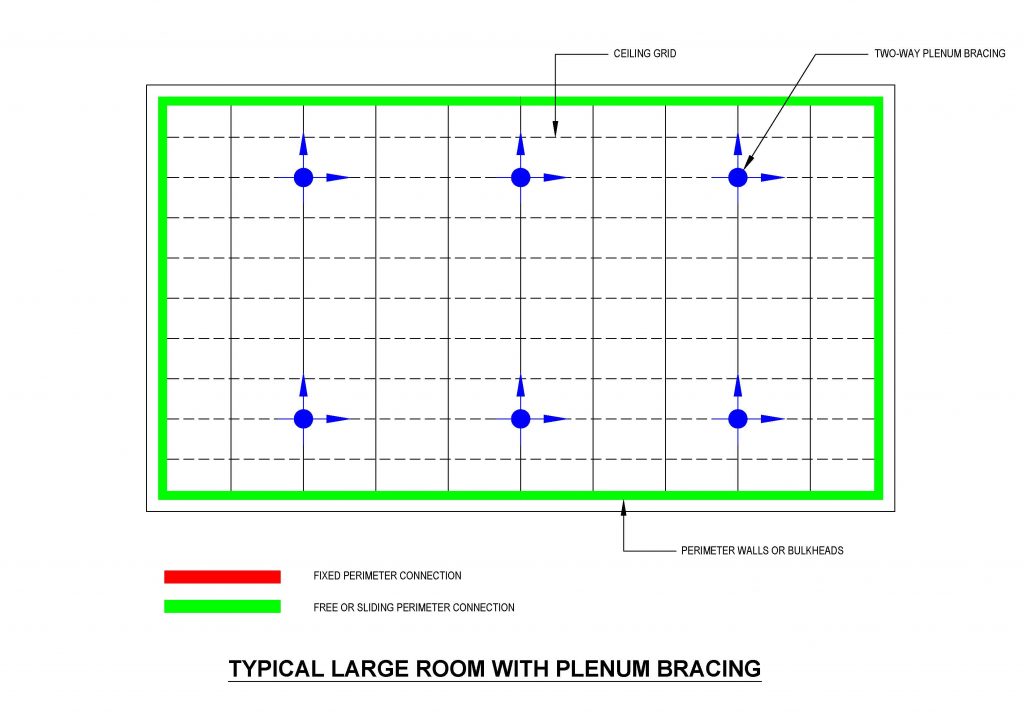
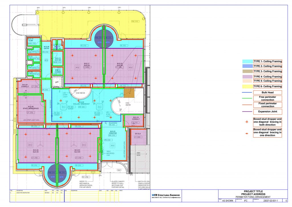
Below is an example of a perimeter fixing and plenum bracing arrangement.
Rondo Key-Lock Conceal Seismic Ceiling or Rondo Duo Seismic Ceiling are perfect examples of the seismic ceilings systems which can be well designed and detailed to meet and satisfy seismic requirements of the AS 1170.4.